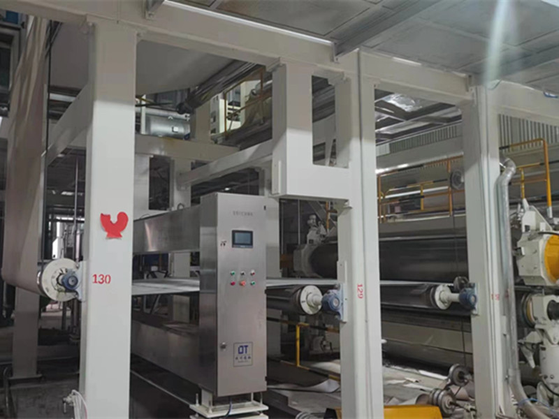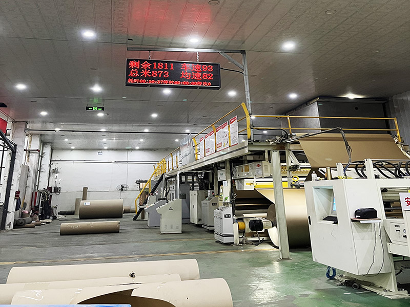
High Speed Centrifugal Fan same name as Turbine fan are core vacuum equipment for paper machines. Driven by high-speed impellers, they generate stable vacuum to facilitate dewatering during papermaking. Featuring variable speed regulation, water-free operation and high efficiency, they outperform traditional liquid ring pumps. With reliable performance, low maintenance and heat recovery capability, they are widely applied in modern paper production lines for energy-saving operation.
Payment :
T/TColor :
As Customer RequiredShipping Port :
China PortLead Time :
One MonthMin. order :
1 Set1. High speed centrifugal fan parameters
|
Item |
High speed centrifugal fan parameters |
Notes |
|
Equipment model |
GLFⅡD315/1.50 |
|
|
Inspiratory medium |
Saturated air |
|
|
Local air pressure |
101kpa |
|
|
Inlet temperature |
35℃ |
|
|
(free side) Inlet flow |
340m3/min |
|
|
Free side vacuum degree |
45KPa |
|
|
Vacuum point location |
3 |
|
|
Outlet pressure (G) |
Normal (≤2kPa) |
|
|
High speed shaft speed |
23000r//min |
|
|
Design point power |
259kw |
|
|
Motor power |
315kw / 2P |
|
|
Outlet temperature |
Around 110℃ |
|
|
Motor side air volume |
|
|
|
Motor |
|
|
|
Rated frequency of the motor |
50hz |
|
|
Voltage |
380v |
|
|
motor speed |
2980rpm |
|
|
Motor side vacuum degree |
|
|
|
Drive |
Motor and gear box |
|
|
Shaft seal form |
Labyrinth Seal |
|
|
Bearing model |
With bush |
|
|
Bearing lubrication |
Grease |
|
|
Oil grade |
46# Turbine oil |
|
|
Bearing cooling |
Oil cooling |
|
|
Coupling model (with middle part) |
Diaphragm coupling |
|
|
Oil cooler type |
Tubular heat exchanger |
|
2. turbine fan supply list
|
name |
Specification and model |
number |
Manufacturer
|
notes |
|
Main engine single pump |
GLFⅡD315/1.45 |
1 |
Hangzhou Sixin |
With anchor bolts |
|
Integrated lubricating oil control system, base and oil temperature, oil pressure, and vibration detection |
||||
|
Asynchronous motor(25-50Hz) |
315kw-2P |
1 |
zhongqing |
380V/50HZ |
|
Variable frequency control cabinet |
GD200A-355G |
1 |
Invt |
380V/50HZ |
|
Including circuit breakers and reactors |
||||
|
Vibration Monitoring |
HZD-Z |
2 |
Wuxi Houde |
0~200μm |
|
Pressure transmitter |
3151TGP |
1 |
Rosemount/huaheng/ jinhu huanghe |
-100kPa~100kPa |
|
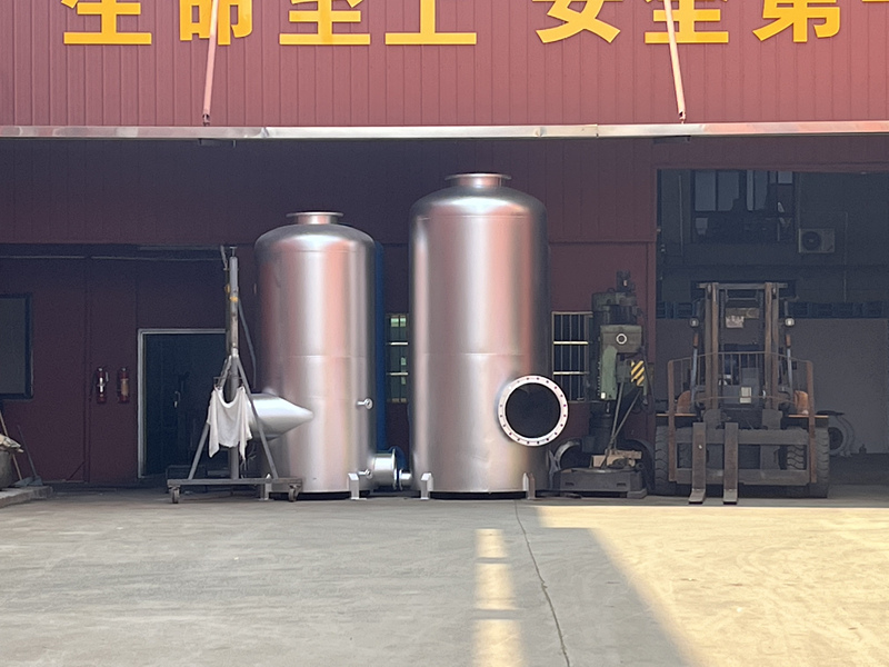
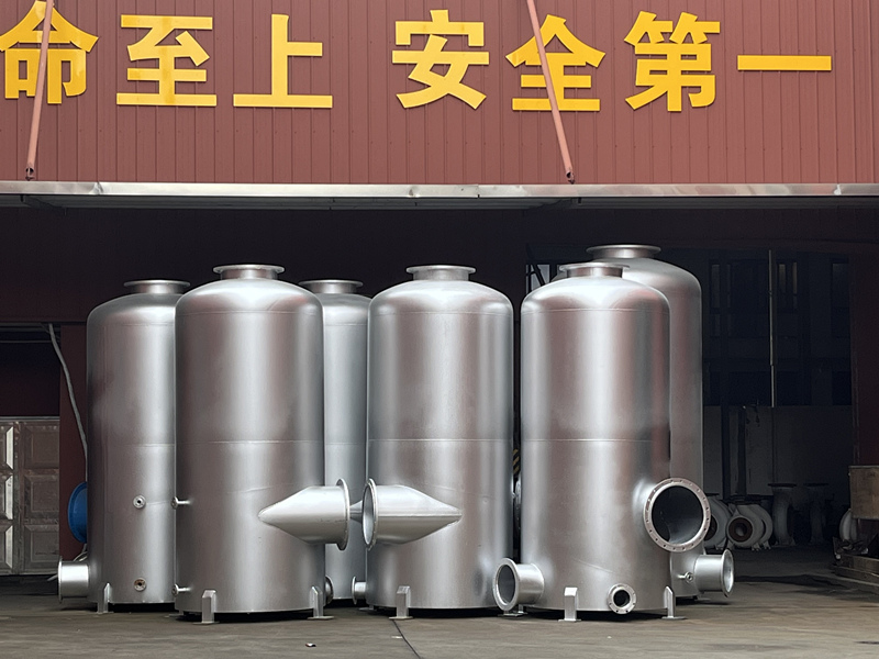
expansion joint
|
|
2 |
Dongtai SS |
PN1.0 |
|
Bypass filter |
DN150 |
1 |
Hangzhou Sixin |
|
|
Including 90 ° bend, filter screen, and electric butterfly valve |
||||
|
Pipeline air filter screen |
DN600 |
1 |
Hangzhou Sixin |
stainless steel |
|
muffler |
DN500 |
1 |
Hangzhou Sixin |
|
3. Technical Description of High Speed Centrifugal Fan Unit
3.1 Unit Overview
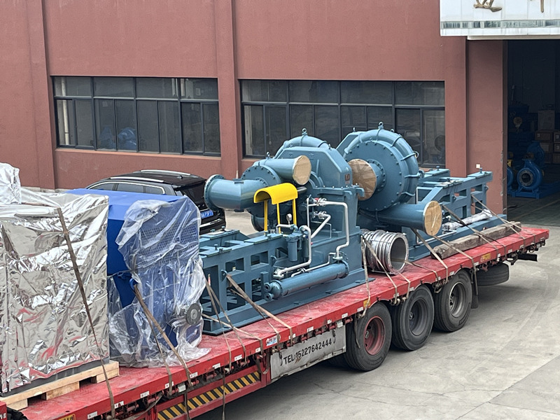
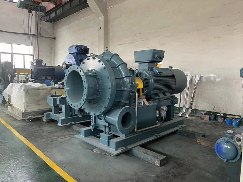
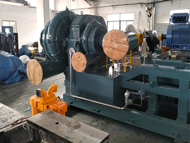
This high-speed centrifugal fan is a horizontal centrifugal structure, with the unit arranged on one floor and the intake and exhaust pipes arranged horizontally. The main engine consists of a main engine, a speed increase gearbox, a drive motor, and a diaphragm coupling. The centrifugal fan impeller is arranged in a single stage, consisting of a volute, volute inner body, static wheel cover, and impeller, forming a cylindrical structure, installed on one side of the speed increase box. The speed increaser is a parallel shaft helical gear first stage speed increaser. The coupling is a diaphragm type coupling. The driving motor is a Y series three-phase asynchronous variable frequency motor. The high-speed shaft rotor is equipped with a single impeller and labyrinth seal.
The centrifugal fan, gearbox, and drive motor are arranged on the same common base. Expansion joints are installed on the inlet and outlet pipelines to absorb the thermal expansion of the pipeline.
3.2 Main technical parameters of centrifugal fan (see data sheet)
3.3 Quantity:4 sets of high-speed centrifugal fans and accessories
3.4 Drive form: three-phase asynchronous variable frequency motor through diaphragm coupling
3.5 Flow regulation method: frequency converter control
4. High speed centrifugal fan host
4.1 Impeller: The material is made of high-strength and corrosion-resistant high-quality steel, which is milled into one shape through five axes. The blade profile design adopts a three-dimensional flow design. During the production process, multiple heat treatments and flaw detection treatments are carried out. After finishing, it undergoes an overspeed test at 1.2 times the working speed.
4.2 Rotordynamic analysis: Using rotor stability analysis and calculation, the critical speed diagram considering the influence of bearing and support elasticity, as well as the calculation technology considering the unbalanced mass distribution, support damping, and airflow disturbance on the rotor's unbalanced response, ensures the stability of the rotor. Adopting diaphragm type couplings to improve the torsional characteristics of the entire rotor.
4.3 The gearbox is made of cast iron, and the gears are parallel shaft single helical teeth. High quality steel is selected for carburizing, quenching, shaping, and grinding processing.
The tooth surface hardness is HRC58-62, and the machining accuracy is GB10095-88 level 4.
4.4 Bearings: Dynamic sliding bearings are used.
4.5 Corresponding to the comb seal and the stationary components at the inlet end of the impeller, soft media is used to ensure the minimum operating clearance, while also preventing collisions between the dynamic and static components that may damage the main engine when the rotor is unstable.
4.6 Sealing: Adopting a labyrinth structure.
4.7 Lubricating oil system: adopt containerized type. Share the base with the host. It consists of an oil tank (integrated on the bottom), an oil pump, an oil cooler, an oil filter, an overflow valve, an electric heater, and a one-way valve. The equipment layout is compact and reasonable, and operation and maintenance are very convenient. The main oil pump is installed on the low-speed shaft of the booster, and the auxiliary oil pump is placed below the main motor. Pressure interlocking is carried out between the main and auxiliary oil pumps to effectively ensure the normal operation of the system. The dual core oil filter can ensure the replacement of the oil filter without stopping the machine.
4.8 Oil cooler: The cooler has two tube passes, with cooling water passing through the tube pass and oil passing through the shell pass.
4.9 Materials of Main Components of High Speed Centrifugal Fan
Spiral case, inner body of spiral case: ZG25
Impeller: 7424 or titanium alloy
High speed gear shaft:12Cr2Ni4
Low speed gears:20CrMnTi
Booster box:QT600
Unit common base: square steel Q235A
High Speed Centrifugal Fan same name as Turbine fan are core vacuum equipment for paper machines. Driven by high-speed impellers, they generate stable vacuum to facilitate dewatering during papermaking. Featuring variable speed regulation, water-free operation and high efficiency, they outperform traditional liquid ring pumps. With reliable performance, low maintenance and heat recovery capability, they are widely applied in modern paper production lines for energy-saving operation.
Learn More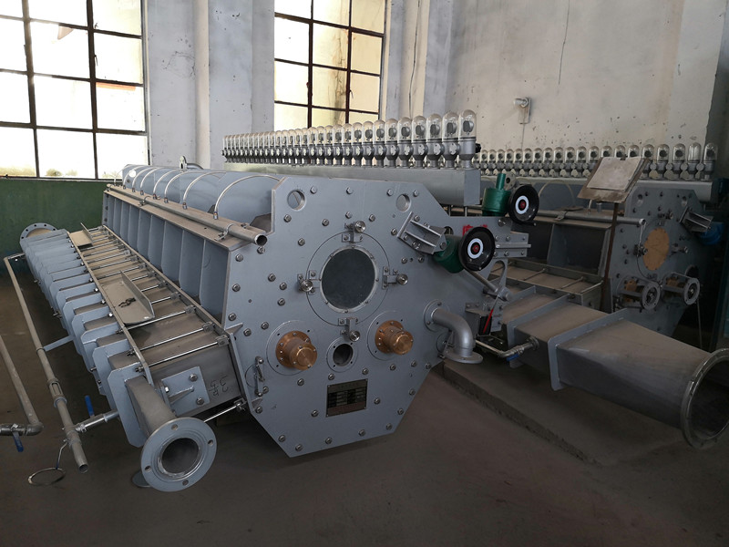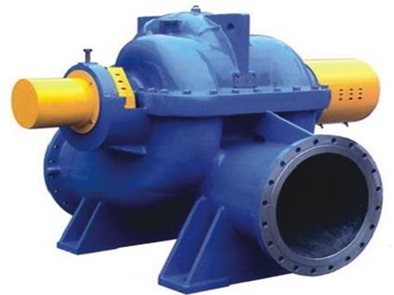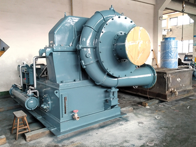
High Speed Centrifugal Fan same name as Turbine fan are core vacuum equipment for paper machines. Driven by high-speed impellers, they generate stable vacuum to facilitate dewatering during papermaking. Featuring variable speed regulation, water-free operation and high efficiency, they outperform traditional liquid ring pumps. With reliable performance, low maintenance and heat recovery capability, they are widely applied in modern paper production lines for energy-saving operation.
Learn More Newsletter
 +86 -18039135891
 annyzvv@163.com
snowfoxmachinery@outlook.com
annyzvv@163.com
snowfoxmachinery@outlook.com
 Address: 95 North of Jingsan Rd, Jinshui Dist, Zhengzhou,China
 IPv6 network supported